1. 서 론
지난 5년간(2015~2019) 국가화재정보센터에 접수된 계절용 기기의 화재 건수중 열선으로 인한 화재는 화목보일러 화재 건수에 뒤를 이어 2번째로 많은 빈도수를 차지하였다. 하지만 화목보일러는 64.3% (184건)가 부주의에 의한 화재인 반면, 열선은 56.5% (152건)가 전기적 요인에 의한 실화였다.
이처럼 계절용 기기 가운데 전기적 요인에 의한 화재 비중이 가장 높은 열선은 “전기용품 및 생활용품 안전관리법”에 의한 안전인증 대상 제품이며, 전기용품 안전기준의 적합성 평가 기준에 따라 관리되고 있다. 하지만, 열선 화재는 매년 꾸준한 증가 추세를 보이고 있고, 이를 위한 화재예방 대책으로 기술기준 보완이 절실히 요구되고 있는 실정이다. 그러나, 해당 기술기준에 의한 적합성 평가기준과 실제 사용사례에 의한 비교 연구자료가 없어 이에 따른 기술기준 검토 요구자료 마련을 위한 실험이 필요하였다.
따라서 본 연구에서는 열선에 대한 전기용품 안전기준에 의한 시험조건과 실제 사용사례를 비교하고, 안전기준과 실제 사용사례를 적용한 재현실험을 통해 열선에 대한 온도 차이를 비교 분석하여 화재 예방 강화 방안을 도출하고자 한다.
2. 본 론
2.1 화재통계 분석
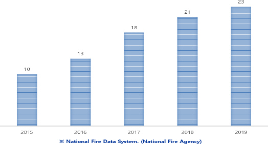
2015년부터 2019년까지 5년간 열선으로 인한 화재사고 가운데 원인 미상과 복합적인 요소 및 일반전선에 의한 화재와 같은 간접요인을 제외하고, 수도동결방지기(열선)에서 발화된 직접적인 화재요인만을 추려 화재 발생 건수를 확인해보면
Figure 1과 같이 화재 발생 추이는 매년 꾸준한 증가 추세를 보이고 있다.
Figure 1
Anti-freeze electric heating cable fire statistics.
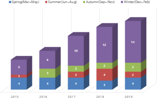
이를 좀 더 세분화하여 계절별로 화재발생현황을 그래프로 분석해 보면, 수도동결방지기(열선)의 제품 특성상 상대적으로 겨울철에 많은 빈도수를 차지하기는 하지만, 반드시 겨울철에만 화재가 발생한 것은 아니였다. 이는 수도동결방지기(열선)가 겨울철에만 사용되는 것이 아니라, 다양한 용도로 1년 내내 상시전원에 의해 사용되고 있다는 것을
Figure 2와 같은 통계자료를 통해 확인할 수 있었다.
Figure 2
Seasonal fire occurrence statistics.
2.2 화재사례 분석
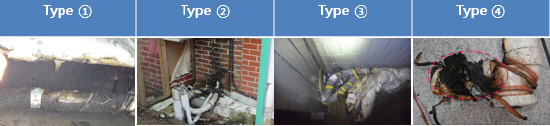
국가화재정보시스템을 통해 수도동결방지기(열선)의 화재사례를 종합해 볼 때,
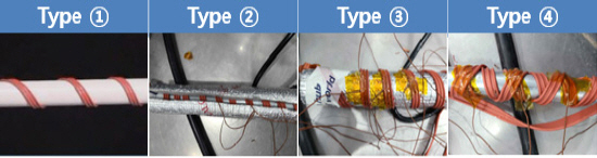
Figure 3과 같이 총 4가지 설치 사례들로 정리할 수 있었다(
1). ➀ 수도 파이프에 열선을 일정한 간격으로 감은 상태, ➁ 수도 파이프에 열선을 감고 그 겉면에 보온재를 감싼 상태, ➂ 수도 파이프에 보온재를 감싸고 그 겉면에 열선을 감은 상태, ➃ 수도 파이프에 열선만 불규칙하게 감겨진 상태.
Figure 3
이 가운데
Figure 4의 연도별 설치 사례에 따른 화재발생 현황을 분석해 보면, “➁ 수도 파이프에 열선을 감고, 그 겉면에 보온재를 감싼 상태”가 가장 높은 비중을 차지하였고, 그 뒤를 이어 ➀-➂-➃ 순으로 나타났다.
Figure 4
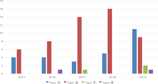
이와 같은 설치 조건은 실험기준 반영을 위한 가장 큰 요소로 판단하고, 본 실험에서의 중요한 실험조건으로 기준 계획을 수립하였다.
2.3 제품구조 분석
수도동결방지기(열선)의 분류는
Table 1과 같이 용도별(시설, 단품), 타입별(일반형, 삽입형 등), 재질별(PVC, 실리콘 등), 제어방식별(정온방식, 센서방식) 등의 형태로 구분할 수 있다(
2).
Table 1
Anti-Feeeze Electric Heating Cabel Classification
|
Purpose |
Division |
Explanation |
Note |
|
Use |
Building equipment |
Products installed in facilities or facilities such as buildings |
※ Not applicable to electrical and daily necessities safety laws. |
|
Household |
Products that can be easily installed by the general public |
|
|
Type |
General type |
Products used by winding around other pipes |
|
|
Insert type |
Products to be installed by inserting them inside the piping |
|
|
Material |
PVC |
Classification by heater outer skin material |
|
|
Silicon |
|
|
Control method |
Constant temperature method |
A method that voluntarily controls the current based on the resistance of the heat ray |
|
|
Sensor method |
A method of controlling the current via a temperature sensor |
|
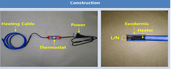
또한, 수도동결방지기(열선)의 제품구조는 제어방식에 따라 정온방식과 센서방식으로 분류할 수 있으며, 제품에 대한 구조는
Figure 5와 같다(
3).
Figure 5
Anti-freeze electric heating cable structure.
2.4 실험조건
수도동결방지기(열선)의 실험조건은 전기용품 안전기준(K60335-1, K10013)을 준용한 Tables
2~
4의 시험조건을 기본으로 적용하였으나, K 10013의 11.7항 시험조건에서 “관에 붙여 사용하는 것에 있어서는 시험품의 철판에 통상 사용상태로 부착” 하는 조건 대신 ➀ 수도 파이프에 열선을 일정한 간격으로 감은 상태, ➁ 수도 파이프에 열선을 감고 그 겉면에 보온재를 감싼 상태, ➂ 수도 파이프에 보온재를 감싸고 그 겉면에 열선을 감은 상태, ➃ 수도 파이프에 열선만 불규칙하게 감겨진 상태를
Figure 6과 같은 실험조건으로 대체하여 적용하였다(
4,
5).
Table 2
Household and Similar Electrical Appliances - Safety Standards (General Conditions for the Tests)
|
K 60335-1 |
K 10013 |
|
5. General conditions for the test |
4. General conditions for the test |
|
Unless otherwise specified, the tests are carried out in accordance with this clause. |
This clause of Part 1 is applicable except as follows. |
|
5.5 The tests are carried out with the appliance or any movable part of it placed in the most unfavourable position that may occur in normal use. |
4.7 Addition:
The test of Clauses 10, 11 and 19 are carried out at the most unfavourable ambient temperature within the range of -10 to 5 °C |
5.7 The tests are carried out in a draught-free location at an ambient temperature of 20 ± 5 °C.
Ifthe temperature attained by any part is limited by a temperature sensitive device or is influenced by the temperature at which a change of state occurs, for example when water boils, the ambient temperature is maintained at 23 ± 2 °C in case of doubt. |
|
|
5.10 The tests are carried out on the appliance as supplied. However, an appliance constructed as a single appliance but supplied in a number of units is tested after assembly in accordance with the instructions provided with the appliance. |
|
Table 3
Household and Similar Electrical Appliances - Safety Standards (Heating)
|
K 60335-1 |
K 10013 |
11. Heating
11.2 Built-in appliances are installed in accordance with the instructions.
Other heating appliances and other combined appliances are placed in a test corner as follows:
appliances normally placed on a floor or table in use, are placed on the floor as near to the walls as possible;
appliances normally fixed to a wall are fixed to one of the walls, as near to the other wall and floor or ceiling as is likely to occur, taking into account the instructions;
appliances normally fixed to a ceiling are fixed to the ceiling as near to the walls as is likely to occur, taking into account in the instructions. |
11. Heating
This clause of Part 1 is applicable except as follows.
11.2 This clause of Part 1 is applicable except as follows.
11.4 This clause of Part 1 is applicable except as follows.
11.7 Replacement: Underwater equipemet operates by sumerging it in water, and when used by attaching it to a pipe, it operates by adhering to a fla iron plate.
Others are operated by attaching them to a flat wooden board with a thickness of 10 mm or maore. |
|
11.3 As far as is possible, the appliance is positioned so that the thermocouples detec the highest temperatures. |
For devices with an automatic temperature controller, set the set temperature to the maximum temperature. |
|
11.4 Heating appliances are operated under normal operation and at 1,15 times rated power input. |
|
|
11.7 The appliance is operated for a duration corresponding to the most unfavourable conditions of normal use. |
|
|
NOTE The duration of the test may consist of more than one cycle of operation. |
|
Figure 6
실험용 샘플 선정은 온‧오프라인에서 유통되고 있는 수도동결방지기(열선) 10개를 무작위로 선별하였으며, 동일한 조건의 비교실험을 위해 다음과 같은 형태의 열선으로 한정하였다.
‧⋅용도: 건축물 시설에 시공하는 제품이 아닌 일반인에 의해 쉽게 설치가 가능한 제품
⋅타입: 수도 배관에 삽입하거나 밴드형 또는 면상형이 아닌 배관 외부에 감아서 사용하는 일반형(열선) 제품
2.5 실험결과
본 실험에 적용한 실험장비는 일정한 실험환경 유지를 위한 온‧습도 워크인챔버, 온도측정을 위한 디지털 온도기록계, 전압조정을 위한 CVCF, 슬라이닥스 및 디지털 파워메터, 실험전 제품결함 확인을 위한 내전압시험기 등을 사용하였다.
“2.4 실험조건”에 따른 실험 결과,
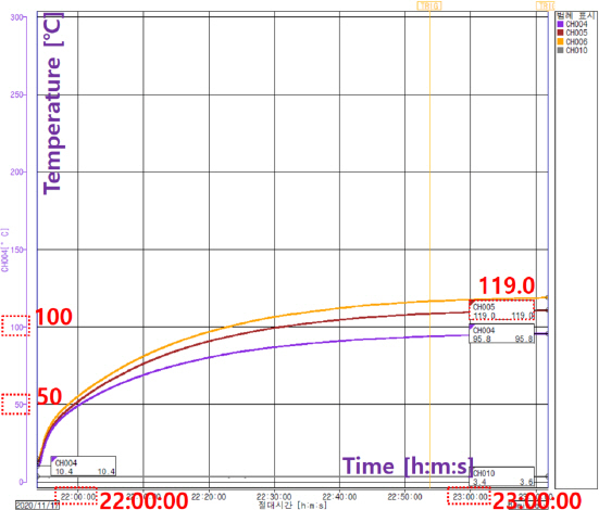
Table 5에 있는 Type ➀의 실험 결과와 같이 실험 샘플별 온도상승(11항)과 이상운전(19.101항)의 온도 편차는 1번 샘플과 2번 샘플을 제외하고 큰 온도차가 발생하지는 않았으며, 10개의 열선 샘플간 최대 온도차이는 약 58 °C (최저: 샘플9-21.5 °C, 최고: 샘플5-79.0 °C) 차이를 보였다. 또한, 4가지 설치 사례 가운데 가장 큰 온도상승에 대한 조건은 사례➁(수도 파이프에 열선을 감고, 그 겉면에 보온재를 감은상태)였으며, 5번 샘플은 온도상승(11항) 대비 이상운전(19항)의 온도차이가 40 °C (11항: 79.0 °C, 19.101항: 119.0 °C)로 가장 큰 차이가 발생하는 샘플이었다.
Figure 7은 5번 샘플의 11항(온도상승시험)이고,
Figure 8은 동일 샘플의 19.101항(이상운전시험)의 온도상승 그래프이다.
Table 4
Household and Similar Electrical Appliances - Safety Standards (Abnormal Operation)
|
K 60335-1 |
K 10013 |
|
19. Abnormal operation |
19. Abnormal operation |
19.1 Appliances shall be constructed so that as a result of abnormal or careless operation, the risk of fire, mechanical damage impairing ssfety or protection against electric shock is obviated as far as is practicable.
Electronic circuits shall be designed and applied so that a fault condition will not render the appliance unsafe with regard to electric shock, fire hazard, mechanical hazard or dangerous malfunction. |
This clause of Part 1 is applicable except as follows.
19.1 This clause of Part 1 is applicable except as follows.
19.101 Procucts that are wound on a pipe are attached to a flat iron plates and operated. Others are operated by attaching them to a flat wooden board with a thickness of 10 mm or maore. |
|
Unless otherwise specified, the tests are continued until a non-self-resetting thermal cut-out operates or until steady conditions are established. If a heating element or an intentionally weak part becomes permanently open-circuited, the relevant test is repeated on a second sample. This second test shall be terminated in the same mode unless the test is otherwise satisfactorily completed. |
|
|
19.4 The appliance is tested under the conditions specified in clause 11. |
|
|
19.101 Blank |
|
Table 5
|
Sample No |
11. Heating |
19.101. Abnormal operation |
|
Type ➀ |
Type ➁ |
Type ➂ |
Type ➃ |
|
1 |
68.4 |
55.3 |
65.2 |
56.5 |
64.3 |
|
2 |
30.4 |
47.5 |
52.2 |
27.1 |
37.4 |
|
3 |
35.9 |
39.5 |
40.2 |
28.9 |
33.0 |
|
4 |
57.2 |
53.6 |
78.3 |
34.5 |
45.4 |
|
5 |
79.0 |
78.9 |
119.0 |
52.3 |
58.1 |
|
6 |
26.2 |
28.0 |
60.8 |
23.2 |
30.1 |
|
7 |
26.2 |
25.2 |
57.9 |
27.9 |
47.6 |
|
8 |
29.8 |
27.2 |
28.4 |
33.0 |
26.8 |
|
9 |
21.5 |
20.5 |
38.0 |
16.4 |
37.2 |
|
10 |
45.6 |
46.4 |
77.3 |
40.9 |
46.5 |
Figure 7
Temperature graph (No5-Type➀ 11).
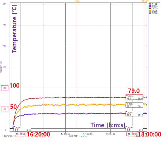
Figure 8
Temperature graph (No5-Type➁ 19.101).
3. 결론 및 고찰
국가화재정보시스템에 등록된 화재조사 결과 보고서에서는 수도동결방지기(열선)와 관련된 화재 대부분이 열선 히터부에서 발생한 전기적 아크(단락)로 출화된 것을 주요인으로 분석하고 있다. 이는 열선 히터 피복에서 경년 열화 또는 물리적 균열로 전기적 발화 요인이 발생한 것이다.
이처럼 수도동결방지기(열선) 열선 피복에 직접적인 요인으로 작용하는 피복제는 화학 성분 배합인지에 따라 열가소성과 열경화성으로 구분할 수 있다. 열가소성은 열은 가하면 원래 상태로 돌아오는 성질이고, 열경화성은 열을 가하면 다른 물질로 바뀌는 성질인데, 열가소성 재료로는 폴리에틸렌(PE), 폴리스타이렌(PS), 염화비닐(PVC), 폴리바이닐플루오라이드(PVF), 폴리메틸메타크릴레이트(PMMA), 폴리에틸렌테레프탈레이트(PET), 폴리아마이드(PA), 에틸렌프로필렌 고무(EPR) 등이 있고, 열경화성 재료로는 페놀수지, 에폭시수지, Si수지, 멜라민수지, 암모니아수지, 폴리미드 수지 등이 있다. 다시 말해, 피복제의 화학 성분 배합비에 따라 유연한 성분과 딱딱한 성분의 장‧단점을 갖게 되는데, 화학 성분의 배합비로 제작된 열선 제품화 이후, 열 또는 외부 물리적 스트레스에 의해 피복에 균열이 생겨 전기적 위험요소가 발생하게 되는 것이다(
6,
7).
따라서, 본 실험을 통해 동결방지열선에 대한 화재예방 강화 방안으로는 해당 전기용품 안전기준(K10013)의 내용상 열선 피복 성분에 따른 온도 제한 또는 내구성에 대한 화재 안전 기능 강화 방안이 마련되어야 하고, 아울러 실제 설치 사례를 적용한 현실적인 시험조건도 함께 검토되어야 할 것으로 보여진다.